最近开始学习了Verilog,之前的学习我也开始意识到记录自己的学习思路的重要性,以便以后的自己可以复盘,也是对自己一段时间学习的总结和回顾
我使用的是HDLBits进行的学习,这里附上链接HDLBits,由于是纯英语网站,所以需要配合浏览器的沉浸式翻译,其实效果也一般,也可以借助AI,不过只用作翻译,不要要求它解答
由于是个人的回顾,所以整体的思路不连贯,仅仅作个人记录
正文
简单介绍
 1
 2
 3
 4
 5
 6
 7
 8
 9
10
11
12
13
14
15
16
17
18
19
20
21
22
23
24
| module counter10(
//端口定义
input rstn, //复位端,低有效
input clk, //输入时钟
output [3:0] cnt, //计数输出
output cout); //溢出位
reg [3:0] cnt_temp ; //计数器寄存器
always@(posedge clk or negedge rstn) begin
if(! rstn)begin //复位时,计时归0
cnt_temp <= 4'b0 ;
end
else if (cnt_temp==4'd9) begin //计时10个cycle时,计时归0
cnt_temp <=4'b000;
end
else begin //计时加1
cnt_temp <= cnt_temp + 1'b1 ;
end
end
assign cout = (cnt_temp==4'd9) ; //输出周期位
assign cnt = cnt_temp ; //输出实时计时器
endmodule
|
这是从菜鸟教程里随便拿的一个代码,大致总结一下基本的语法之类的内容
moudle和endmoule之间的就是一个电路模块,可以理解位编程语言的函数
counter10就是一个电路的名字,方便之后复用
之后会进行端口的定义在**();中间,不同端口之间用,** 分隔开(显然都是英语的符号)
input是输入接口output是输出接口,可以定义线宽
reg,是寄存器类型,wire是线类型,他们中间都能用**[ : ]**来定义线宽,之后就是定义名称
assign相当于连线的意思
之后的always模块就留到之后介绍了
数值种类
Verilog HDL 有下列四种基本的值来表示硬件电路中的电平逻辑:
- 0:逻辑 0 或 “假”
- 1:逻辑 1 或 “真”
- x 或 X:未知
- z 或 Z:高阻
X意味着信号数值的不确定,即在实际电路里,信号可能为 1,也可能为 0。
Z表示高阻状态,字面意思,有很高的阻值
1
2
3
| // 多个设备都想用同一条数据总线
assign data_bus = (enable1) ? data_out1 : 1'bz;
assign data_bus = (enable2) ? data_out2 : 1'bz;
|
- 当
enable1=1:设备1驱动总线 - 当
enable2=1:设备2驱动总线 - 当都不使能:总线处于高阻,谁都没驱动
数值表示
数字声明时,合法的基数格式有 4 中,包括:十进制(’d 或 ‘D),十六进制(‘h 或 ‘H),二进制(‘b 或 ‘B),八进制(‘o 或 ‘O)。数值可指明位宽,也可不指明位宽。
例如:
1
2
| 4'b1011 // 4bit 数值
32'h3022_c0de // 32bit 的数值
|
前面的数字是2进制下的位数,不是该进制下的位数
一般直接写数字时,默认为十进制表示,例如下面的 3 种写法是等效的:
1
2
3
| counter = 'd100 ; //一般会根据编译器自动分频位宽,常见的为32bit
counter = 100 ;
counter = 32'h64 ;
|
常见32bit,需要注意的是如果在不指定位宽的数前面加-,可能会出现问题
具体例子:
mula = -4'd4 ;
在 Verilog 里,-4'd4 并不是直接存 -4 的补码,而是先计算 4’d4 = 0100,然后对整个数取负。
但 0100 作为无符号数是 4,作为有符号数是 +4。-4 的 4位补码应该是 1100(-8 ~ +7 的范围)。
32 位的 -4 是多少?
- 4 的 32 位二进制:
00000000_00000000_00000000_00000100 - 取负(补码):
11111111_11111111_11111111_11111100
所以一定要定义位宽,这是一个好习惯
parameter介绍
parameter 是 Verilog 中用于定义常量的关键字。它允许你在模块内部定义一个编译时确定的值,并且可以在模块实例化时被覆盖(重新定义)。这样可以提高代码的可重用性和可配置性。
基本语法(有比较老的,就不展示了)
1
2
3
| module 模块名 #(parameter 参数名 = 默认值) (
端口列表
);
|
基本使用:
定义位宽
1
2
3
4
5
| module my_register #(parameter WIDTH = 8) (
input clk,
input [WIDTH-1:0] d,
output reg [WIDTH-1:0] q
);
|
定义状态机状态
1
| parameter A = 2'b00, B = 2'b01, C = 2'b10, D = 2'b11;
|
定义延迟时间(仿真用)
1
2
| parameter DELAY = 10;
always #DELAY clk = ~clk;
|
实例化覆盖参数
 1
 2
 3
 4
 5
 6
 7
 8
 9
10
11
12
13
14
15
| // 定义模块
module counter #(parameter MAX = 255) (
input clk,
output reg [7:0] q
);
always @(posedge clk) begin
if (q == MAX)
q <= 0;
else
q <= q + 1;
end
endmodule
// 实例化并覆盖参数
counter #(.MAX(59)) u_counter (clk, q); // 模 60 计数器
|
这样就可以定义一个计数器,只需要在使用的时候确定具体的参数就可以了
| 特性 | 说明 |
|---|
| 作用 | 定义模块内的常量,提高可配置性 |
| 可覆盖 | 是,实例化时可用 #(.PARAM(value)) 覆盖 |
| 作用域 | 模块内部 |
| 替代 | localparam 用于不可覆盖的常量 |
杂项
[ : ] 定义位宽的时候用的小端模式,意思是大数在左边
小端模式是最小位在左侧的意思
多维数组
Verilog指出定义多维数组,和编程语言一样
支持reg 和wire类型的多维数组的定义
integer的使用
1
2
3
4
5
6
| integer j; // 声明一个整数变量 j
always@* begin
for (j=0; j<=3; j=j+1) begin // j 用来控制循环次数
byte1[j] = data1[(j+1)*8 - 1 : j*8];
end
end
|
这里的j就是在always块中充当一个变量,用来描述这个电路功能的变量
特点:
- 在 Verilog 标准里,
integer 的位宽是实现相关的,但绝大多数仿真器和综合工具都把它当作32位有符号整数。 - 如果你在
always 块里用 integer 做循环控制,是可以综合成硬件的。例如上面的代码,综合工具会把它展开成实际的硬件逻辑。
使用{}拼接时要注意拼接时有顺序的
{32{1'b0}} 意思是32个一位2进制的0,可以方便拼接
&&符号是将两边的数作为真假
而&是将两个数的每一位做与运算,注意这一点,其他的逻辑符号类似
异或门的特殊作用:
异或门天然具有“奇偶检测”的特性:多个位异或的结果,正好等于这些位中 1 的个数的奇偶性。
1
2
3
4
| 0 ^ 0 = 0 // 0 个 1 → 0
0 ^ 1 = 1 // 1 个 1 → 1
1 ^ 0 = 1 // 1 个 1 → 1
1 ^ 1 = 0 // 2 个 1 → 0
|
可以利用这种性质做奇偶校验
generate和always的一点区别
目前的粗浅理解,不一定正确
always里面不能放assign,因为块里面的内容是描述硬件行为的,不是具体描述硬件本身的
申明变量的时候必须在always块的开头
块中也不能实例化其他电路,因为他是行为描述,实例化时结构描述,两者语法和语义不同
块里使用<=的非阻值赋值,也就是在这个块里是同时进行赋值的,没有顺序了
generate要使用assign,因为generate是批量生产硬件的语言
当 generate 内的 for 循环包含多条语句或需要被外部引用时,必须给 begin 块命名。
1
2
3
4
5
| generate
for (i = 1; i < 100; i = i + 1) begin // ❌ 缺少块名
full_adder fa (...);
end
endgenerate
|
再补充always中的一点东西,当always块中时组合逻辑电路时
📌 总结
| 特性 | 组合逻辑 always @(*) |
|---|
| 赋值方式 | 阻塞赋值 = |
| 执行顺序 | 顺序执行(与书写顺序一致) |
| 综合结果 | 纯组合逻辑(门电路) |
| 注意事项 | 避免组合环、防止锁存器 |
所以,在组合逻辑的 always 模块中,赋值是有顺序的,这与 Verilog 中过程块(always、initial)的语义一致。
1
| .a(a[i+3:i]) // ❌ 错误:位选择不能是变量
|
Verilog 中,位选择 [i+3:i] 的 高位和低位都必须是常量,不能是变量。
正确做法:用 [i+3 : i] 在 generate 中,i 是 genvar,但 i+3:i 在编译时是常量,实际上可以。不过建议用 [i+3 -: 4] 更清晰。
 1
 2
 3
 4
 5
 6
 7
 8
 9
10
11
12
| genvar i;
generate
for (i = 1; i < 100; i = i + 1) begin : gen_bcd_fadd
bcd_fadd u (
.a(a[i*4+3 : i*4]),
.b(b[i*4+3 : i*4]),
.cin(carry[i-1]),
.cout(carry[i]),
.sum(sum[i*4+3 : i*4])
);
end
endgenerate
|
这样就可以了,因为i*x,最终是一个数字
 1
 2
 3
 4
 5
 6
 7
 8
 9
10
11
12
13
14
15
16
17
18
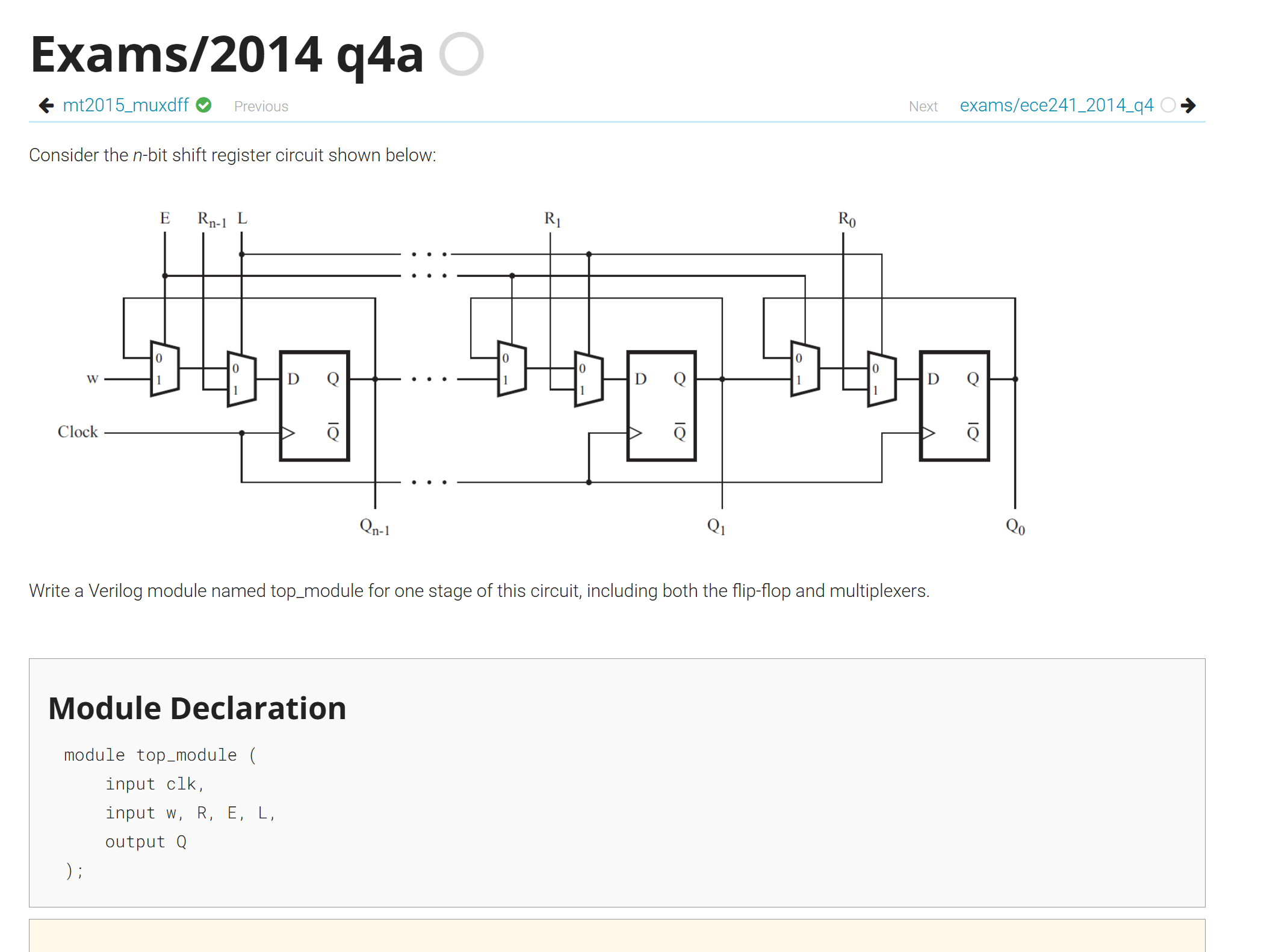
| module top_module (
input clk,
input w, R, E, L,
output Q
);
reg mux;
always@(posedge clk)begin
if(E == 0 && L == 0)
mux <= Q;
else if(E == 1 && L == 0)
mux <= w;
else if(E == 0 && L == 1)
mux <= R;
else if(E == 1 && L == 1)
mux <= R;
end
assign Q = mux;
endmodule
|
这是我的解答过程,以前在logisim模拟的时候会将输出接到输入上去,但这是第一次在Verilog这样子接,以前以为不行,没想道可以
如果单纯的只看这一个电路的话,其实就是Q保持原来的数值
Verilog部分题目的总结
时钟
 1
 2
 3
 4
 5
 6
 7
 8
 9
10
11
12
13
14
15
16
17
18
19
20
21
22
23
24
25
26
27
28
29
30
31
32
33
34
35
36
37
38
39
40
41
42
43
44
45
46
47
48
49
50
51
52
53
54
55
56
57
58
59
60
61
62
63
64
65
66
67
68
69
70
71
72
73
74
75
76
77
78
79
80
81
82
83
84
85
86
87
88
89
90
91
92
93
94
| //60的计数器
module count_60(
input clk,
input reset,
input ena,
output [7:0] out,
output en
);
reg [7:0] temp;
//
always @(posedge clk) begin
if (reset)
temp <= 8'd0;
else if (ena) begin
if (temp == 8'd59)
temp <= 8'd0;
else
temp <= temp + 1'b1;
end
end
//这里最终的输出是使用组合逻辑电路,使能信号不能用寄存器和时序电路来做
assign out = temp;
assign en = (temp == 8'd59) && ena;
endmodule
//把二进制转化为BCD码
module binary_bcd(
input [7:0] bin_in,
output [7:0] bcd_out
);
reg [3:0] ones;
reg [3:0] tens;
//这里使用的也是组合逻辑,避免延迟
integer i;
always@(*)begin
ones = 4'd0;
tens = 4'd0;
for(i=7; i>=0; i=i-1)begin
if(ones >= 4'd5) ones = ones + 4'd3;
if(tens >= 4'd5) tens = tens + 4'd3;
tens = {tens[2:0],ones[3]};
ones = {ones[2:0],bin_in[i]};
end
end
assign bcd_out = {tens,ones};
endmodule
//12的计数器
module count_12(
input clk,
input reset,
input ena,
output [7:0] out,
output en
);
reg [7:0] temp;
always @(posedge clk) begin
if (reset)
temp <= 8'd12;
else if (ena) begin
if (temp == 8'd12)
temp <= 8'd1;
else
temp <= temp + 1'b1;
end
end
assign out = temp;
assign en = (temp == 8'd11) && ena;
endmodule
//顶层电路
module top_module(
input clk,
input reset,
input ena,
output pm,
output [7:0] hh,
output [7:0] mm,
output [7:0] ss);
wire p1,p2,p3;
wire [7:0] temp1,temp2,temp3;//用wire类型,避免寄存器的延迟
//模块化
count_60 u1(clk,reset,ena,temp1,p1);
count_60 u2(clk,reset,p1,temp2,p2);
count_12 u3(clk,reset,p2,temp3,p3);
reg pm_reg;
always @(posedge clk) begin
if (reset)
pm_reg <= 1'b0;
else if (p3)
pm_reg <= ~pm_reg;
end
binary_bcd ss_bcd(temp1,ss);
binary_bcd mm_bcd(temp2,mm);
binary_bcd hh_bcd(temp3,hh);
assign pm = pm_reg;
endmodule
|
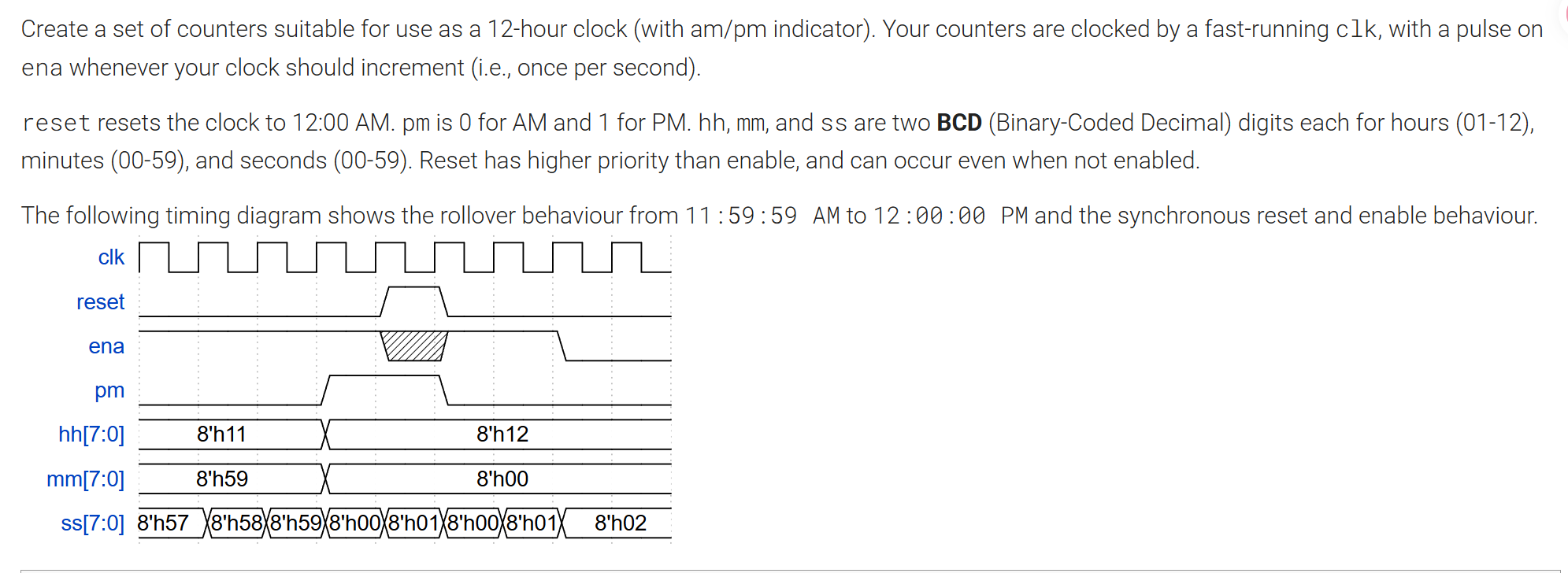
时钟信号处理
目前我感觉时序逻辑在Verilog中比较难处理,最主要的就是寄存器的更新问题,在Verilog中寄存器在时序逻辑中的更新逻辑如下
在时钟边沿到来时,所有赋值语句的右边表达式同时被计算**(采样),然后在边沿结束时统一更新**左边的寄存器。
这就存在一个问题,那就是假如我们存在一个个寄存器temp,我们将一个数据给了temp后,在同一个时钟周期内,temp的值是不能传给其他寄存器或者输出的,不难理解,由于更新逻辑,temp传出去的数据其实是它上一个周期的数据,所以说这样会导致慢一个周期,在设计电路的时候要考虑到这一点
我会用两个例子来说明这一点,先说这一个例子(这个例子是错误的)
 1
 2
 3
 4
 5
 6
 7
 8
 9
10
11
12
13
14
15
16
17
18
19
20
21
22
23
24
25
26
27
28
| module count_60(
input clk,
input reset,
input ena,
output [7:0] out,
output en
);
reg [7:0] temp;
reg temp_en;
always @(posedge clk) begin
if (reset) begin
temp <= 8'd0;
temp_en <= 1'b0;
end
else if (ena) begin
if (temp == 8'd59) begin
temp <= 8'd0;
temp_en <= 1'b1;
end
else begin
temp <= temp + 1'b1;
temp_en <= 1'b0;
end
end
else begin
temp_en <= 1'b0;
end
end
|
我们看这个例子,不难发现这里的使能信号用的是寄存器,这样做是不行的,会慢一个周期
所以说这时候我们就应该使用组合逻辑电路,就能及时更新了。
这里大概总结一下,不能将寄存器视作一个变量,按程序的思维走,它就是电路中的寄存器,只有当遇到上升沿的时候才会更新寄存器的值,而且是所有寄存器同时赋值。如果我们要将一个数值及时更改,就不应该用寄存器。
其实没必要想的太复杂,还记得logisim中有时候将一个电路既接寄存器,也要接输出端吗,放在这里也一样,如果将寄存器再接输出端,
明显就会慢一步,因为组合逻辑电路的值是及时输出的,而寄存器必须要等一个上升沿。
二进制转BCD
这道题还有一个值得说的点,就是这个二进制转BCD,直接看代码:
 1
 2
 3
 4
 5
 6
 7
 8
 9
10
11
12
13
14
15
16
17
18
19
20
| module binary_bcd(
input [7:0] bin_in,
output [7:0] bcd_out
);
reg [3:0] ones;
reg [3:0] tens;
//这里使用的也是组合逻辑,避免延迟
integer i;
always@(*)begin
ones = 4'd0;
tens = 4'd0;
for(i=7; i>=0; i=i-1)begin
if(ones >= 4'd5) ones = ones + 4'd3;
if(tens >= 4'd5) tens = tens + 4'd3;
tens = {tens[2:0],ones[3]};
ones = {ones[2:0],bin_in[i]};
end
end
assign bcd_out = {tens,ones};
endmodule
|
二进制转BCD没有用到寄存器,所以不需要时序逻辑,如果用时序逻辑的话,可能会出现延迟
写电路之前还是要判断需不需要用到时序逻辑,最主要的区别就是电路需不需要之前的状态,如果要用之前的状态,那就一定需要寄存器来存储,反之不需要,这处的逻辑是相通的。
这里可以思考一下,这里的reg真的是寄存器吗?
直接说答案,其实是不是的,always块中使用reg变量是为了满足Verilog的语法要求,实际上这里的
接下来是对二进制转BCD的说明:
先讲一下逻辑:BCD码这里就不说是什么了,我们知道一位BCD码的最大数是1001,就是就,当出现1010的时候就得变为0001_0000
接下来直接举一个例子来说明:
1110(十进制14)
送入最高位得到0001;
送入第二位得到0011;
送入第三位得到0111 > 0100,在0111基础上进行修正,即0111 + 0011 = 1010;
(为什么要这样修正呢,其实是当一个数大于5时,再输入一个数就会使结果大于10,那就一定不是BCD了)
为什么要加3呢,其实这是一个神奇的地方,(abc + 0011)*2+d,即abc X 2+6 + d,红字的部分就直接 ≥ 16 了,超过了4位2进制数表示的范围, 向更高位进一位!那么此时表示十位的BCD码为0001。
在修正的结果上送入第四位得到1_0100,即0001_0100即为1110的BCD码(十进制14)。
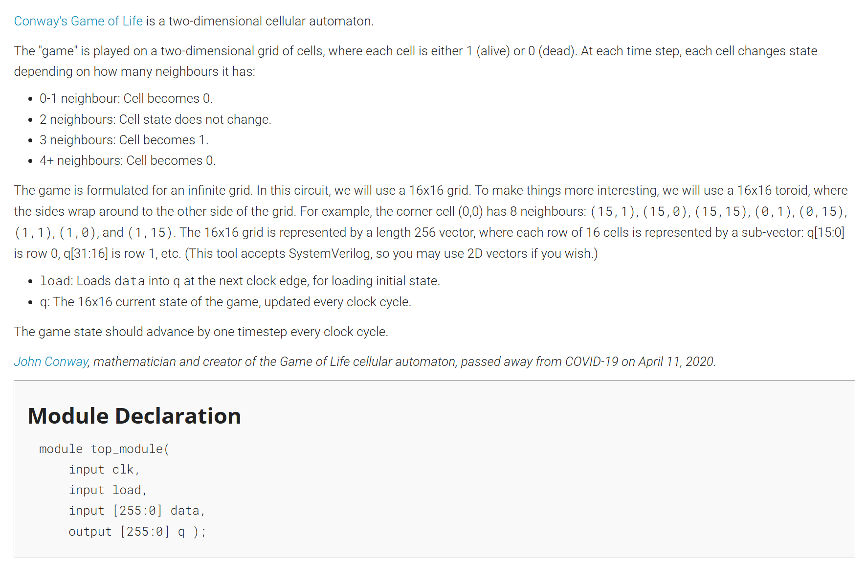
康威生命游戏
这真的是一个很神奇的机器,附上我的解决方法:
 1
 2
 3
 4
 5
 6
 7
 8
 9
10
11
12
13
14
15
16
17
18
19
20
21
22
23
24
25
26
27
28
29
30
31
32
33
34
35
36
37
38
39
40
41
42
| module top_module(
input clk,
input load,
input [255:0] data,
output reg [255:0] q
);
reg temp [15:0][15:0];
reg temp_next [15:0][15:0];
integer i, j;
int sum;
always@(*)begin
for (i = 0; i < 16; i = i + 1) begin
for (j = 0; j < 16; j = j + 1) begin
sum = (temp[(i+1)%16][j] + temp[(i+15)%16][j] +
temp[i][(j+1)%16] + temp[i][(j+15)%16] +
temp[(i+1)%16][(j+1)%16] + temp[(i+1)%16][(j+15)%16] +
temp[(i+15)%16][(j+1)%16] + temp[(i+15)%16][(j+15)%16]);
case (sum)
4'd2: temp_next[i][j] = temp[i][j];
4'd3: temp_next[i][j] = 1'b1;
default: temp_next[i][j] = 1'b0;
endcase
end
end
end
always @(posedge clk) begin
if (load) begin
for (i = 0; i < 16; i = i + 1)
for (j = 0; j < 16; j = j + 1)begin
q[i*16 + j] <= data[i*16 + j];
temp[i][j] <= data[i*16 + j];
end
end
else begin
for (i = 0; i < 16; i = i + 1)
for (j = 0; j < 16; j = j + 1)begin
q[i*16 + j] <= temp_next[i][j];
temp[i][j] <= temp_next[i][j];
end
end
end
endmodule
|
定义i j sum变量的时候使用的是int integer 来定义变量,其实区别不大,这里使用也就是想试试:
在 Verilog 和 SystemVerilog 中,int 和 integer 都表示整数,但有以下关键区别:
| 特性 | integer (Verilog) | int (SystemVerilog) |
|---|
| 位宽 | 32 位(有符号) | 32 位(有符号) |
| 初始值 | x(未知态) | 0(默认值) |
| 声明位置 | 只能在过程块(always、initial)或局部作用域中声明 | 可以在任何地方声明(模块级、过程块、端口、结构体等) |
| 可综合性 | 通常可综合(作为循环变量或临时计算) | 可综合(更现代) |
| 使用场景 | 传统 Verilog 中用于循环控制、中间计算 | SystemVerilog 中通用整数变量,更接近 C 语言的 int |
 1
 2
 3
 4
 5
 6
 7
 8
 9
10
11
12
13
14
15
| always@(*)begin
for (i = 0; i < 16; i = i + 1) begin
for (j = 0; j < 16; j = j + 1) begin
sum = (temp[(i+1)%16][j] + temp[(i+15)%16][j] +
temp[i][(j+1)%16] + temp[i][(j+15)%16] +
temp[(i+1)%16][(j+1)%16] + temp[(i+1)%16][(j+15)%16] +
temp[(i+15)%16][(j+1)%16] + temp[(i+15)%16][(j+15)%16]);
case (sum)
4'd2: temp_next[i][j] = temp[i][j];
4'd3: temp_next[i][j] = 1'b1;
default: temp_next[i][j] = 1'b0;
endcase
end
end
end
|
循环的实现
这里循环是通过取余来实现的,应该不难理解,主要是Verilog要避免复数的行为,所以i-1改成了i+15因为从数学角度来看,这两个数对16同余,这样就实现了循环
循环的优化
 1
 2
 3
 4
 5
 6
 7
 8
 9
10
11
12
13
14
15
16
| always@(*)begin
for (i = 0; i < 16; i = i + 1) begin
for (j = 0; j < 16; j = j + 1) begin
// 使用位与代替 %16
sum = (temp[(i+1) & 15][j] + temp[(i+15) & 15][j] +
temp[i][(j+1) & 15] + temp[i][(j+15) & 15] +
temp[(i+1) & 15][(j+1) & 15] + temp[(i+1) & 15][(j+15) & 15] +
temp[(i+15) & 15][(j+1) & 15] + temp[(i+15) & 15][(j+15) & 15]);
case (sum)
4'd2: temp_next[i][j] = temp[i][j];
4'd3: temp_next[i][j] = 1'b1;
default: temp_next[i][j] = 1'b0;
endcase
end
end
end
|
这里的循环使用与门实现的,大概解释一下:
- 16 的二进制是
1 0000(5 位,1 后面 4 个 0)。 - 任何一个整数除以 16 的余数,只取决于这个数的低 4 位(因为高位都是 16 的整数倍)。
- 例如:
(i+1) % 16 的结果就是 (i+1) 这个数的低 4 位。 - 提取低 4 位的方法:用
& 15(15 的二进制是 0 1111),按位与操作会把高位全部清零,只保留低 4 位。
上述方法适用于所有2的倍数的情况
时序逻辑部分
 1
 2
 3
 4
 5
 6
 7
 8
 9
10
11
12
13
14
15
16
| always @(posedge clk) begin
if (load) begin
for (i = 0; i < 16; i = i + 1)
for (j = 0; j < 16; j = j + 1)begin
q[i*16 + j] <= data[i*16 + j];
temp[i][j] <= data[i*16 + j];
end
end
else begin
for (i = 0; i < 16; i = i + 1)
for (j = 0; j < 16; j = j + 1)begin
q[i*16 + j] <= temp_next[i][j];
temp[i][j] <= temp_next[i][j];
end
end
end
|
时序逻辑这一块之前又出现延迟了,这次算是真正搞清楚了,我们为什么需要时序逻辑?粗浅的理解就是这里需要寄存器,我们必须将细胞的状态存储在寄存器中,因为细胞下一刻的状态与现在细胞的状态有关,所以需要将这存储起来,这里temp_next既要接输出,又要接寄存器,就是这么一个道理
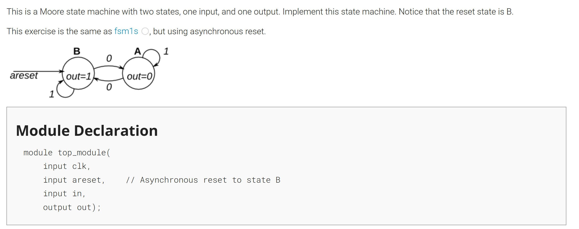
状态机
 1
 2
 3
 4
 5
 6
 7
 8
 9
10
11
12
13
14
15
16
17
18
19
20
21
22
23
24
25
26
27
| module top_module(
input clk,
input areset, // Asynchronous reset to state B
input in,
output out);//
parameter A=0, B=1;
reg state, next_state;
always @(*) begin // This is a combinational always block
// State transition logic
if(in)
next_state = state;
else
next_state = ~state;
end
always @(posedge clk) begin // This is a sequential always block
// State flip-flops with asynchronous reset
if(areset)begin
state <= 1'b1;
end
else begin
state <= next_state;
end
end
assign out = ~(~state & ~areset);
endmodule
|
说实话,这个bug真的很抽象
直接看错误的逻辑图:
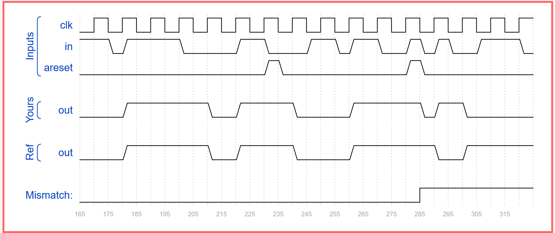
错误的原因
assign out = ~(~state & ~areset);
就是这句话,当in和areset同时发生变化时,state由于clk没有到时钟结束,所以state的状态没变,但由于areset发生了变化,所以assign out = ~(~state & ~areset)这句话执行了,导致了错误
这是因为这道题要求的是异步复位
看正确的代码:
 1
 2
 3
 4
 5
 6
 7
 8
 9
10
11
12
13
14
15
16
17
18
19
20
21
22
23
24
25
26
27
| module top_module(
input clk,
input areset, // Asynchronous reset to state B
input in,
output out);//
parameter A=0, B=1;
reg state, next_state;
always @(*) begin // This is a combinational always block
// State transition logic
if(in)
next_state = state;
else
next_state = ~state;
end
always @(posedge clk,posedge areset) begin // This is a sequential always block
// State flip-flops with asynchronous reset
if(areset)begin
state <= 1'b1;
end
else begin
state <= next_state;
end
end
assign out = state);
endmodule
|
可以发现更改的只有时钟沿:
posedge areset 表示复位信号 areset 的上升沿会立即触发 always 块,不受时钟控制。- 当
areset 为高时,state 被强制赋值为 B,这就是异步复位的含义:复位信号可以随时(与时钟无关)将状态清零。
| 复位类型 | 敏感列表 | 复位行为 |
|---|
| 异步复位 | @(posedge clk, posedge reset) | 复位信号立即生效,与时钟无关 |
| 同步复位 | @(posedge clk) | 复位信号只在时钟边沿生效 |
状态机遇到的一个bug
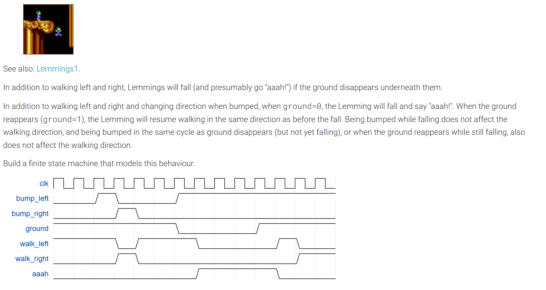
自己写的代码:
 1
 2
 3
 4
 5
 6
 7
 8
 9
10
11
12
13
14
15
16
17
18
19
20
21
22
23
24
25
26
27
28
29
30
31
32
33
34
35
36
37
38
39
40
| module top_module(
input clk,
input areset, // Freshly brainwashed Lemmings walk left.
input bump_left,
input bump_right,
input ground,
output walk_left,
output walk_right,
output aaah );
parameter right = 0,left = 1;
reg state,next_state;
reg temp_ground;
always@(*)begin
case(state)
right: next_state = bump_right ? left : right;
left: next_state = bump_left ? right : left;
default: next_state = state;
endcase
end
always@(posedge clk,posedge areset)begin
if(areset)begin
state <= left;
temp_ground <= 1'b1;
aaah <= 1'b0;
end
else begin
temp_ground = ground;
if(ground)begin
aaah <= 1'b0;
state <= next_state;
end
else begin
aaah <= 1'b1;
state <= state;
end
end
end
assign walk_left = (state == left) && temp_ground;
assign walk_right = (state == right) && temp_ground;
endmodule
|
网上找的答案:
 1
 2
 3
 4
 5
 6
 7
 8
 9
10
11
12
13
14
15
16
17
18
19
20
21
22
23
24
25
26
27
28
29
30
31
32
33
34
35
36
37
38
| module top_module(
input clk,
input areset, // Freshly brainwashed Lemmings walk left.
input bump_left,
input bump_right,
input ground,
output walk_left,
output walk_right,
output aaah );
parameter left=0,right=1,fl=2,fr=3;
reg [1:0] state,next_state;
always @(posedge clk, posedge areset) begin
if (areset)
state<=left;
else
state<=next_state;
end
always @(*) begin
case(state)
left: next_state=ground?(bump_left?right:left):fl;
right: next_state=ground?(bump_right?left:right):fr;
fl: next_state=ground?left:fl;
fr: next_state=ground?right:fr;
endcase
end
assign walk_left=(state==left);
assign walk_right=(state==right);
assign aaah=(state==fr)|(state==fl);//不能写成aaah=(state==fr|fl),这样结果不对,但我不知道为什么,请看到这段代码的人留言告诉我一声,万分感谢。
endmodule
|
思考后更改的答案:
 1
 2
 3
 4
 5
 6
 7
 8
 9
10
11
12
13
14
15
16
17
18
19
20
21
22
23
24
25
26
27
28
29
30
31
32
33
34
35
36
37
38
39
40
41
42
43
| module top_module(
input clk,
input areset, // Freshly brainwashed Lemmings walk left.
input bump_left,
input bump_right,
input ground,
output walk_left,
output walk_right,
output aaah );
parameter right = 0,left = 1;
reg state,next_state;
reg temp_ground;
always@(*)begin
if(temp_ground)begin
case(state)
right: next_state = bump_right ? left : right;
left: next_state = bump_left ? right : left;
default: next_state = state;
endcase
end
else next_state = state;
end
always@(posedge clk,posedge areset)begin
if(areset)begin
state <= left;
temp_ground <= 1'b1;
aaah <= 1'b0;
end
else begin
temp_ground = ground;
if(ground)begin
aaah <= 1'b0;
state <= next_state;
end
else begin
aaah <= 1'b1;
state <= state;
end
end
end
assign walk_left = (state == left) && temp_ground;
assign walk_right = (state == right) && temp_ground;
endmodule
|
其实先夸一下网上找的解法,他将下落也视作了一种状态,其实我的解法一点也不好,并没有理解状态这么一个东西,但仍有值得思考的地方:
1
2
| assign walk_left = (state == left) && temp_ground;
assign walk_right = (state == right) && temp_ground;
|
- 我们先分析这么一段,以前我直接与的是
ground信号,出现了问题,为什么呢?
assign是连续赋值, 所以只要等号右侧的值无论是谁发生改变,就会立即发生改变。
那就必须要注意左侧的所有变量的值要同时发生改变(大部分情况),所以左侧都是寄存器类型的变量,都在一个周期结束后被赋值,其实就是避免的毛刺现象
状态机题目引发的延迟和毛刺现象的思考
错误的代码:
 1
 2
 3
 4
 5
 6
 7
 8
 9
10
11
12
13
14
15
16
17
18
19
20
21
22
23
24
25
26
27
28
29
30
| module top_module(
input clk,
input [7:0] in,
input reset, // Synchronous reset
output [23:0] out_bytes,
output done); //
reg [2:0] state,next_state;
parameter state1 = 3'd1,state2 = 3'd2,state3 = 3'd3,state4 = 3'd4;
always@(*)begin
case(state)
state1: next_state = in[3]? state2 : state1;
state2: next_state = state3;
state3: next_state = state4;
state4: next_state = in[3]? state2 : state1;
endcase
end
always@(posedge clk)begin
if(reset) state <= state1;
else state <= next_state;
end
assign done = (state == state4);
always@(*)begin
case(state)
state1: out_bytes[23:16] = in;
state2: out_bytes[15:8] = in;
state3: out_bytes[7:0] = in;
state4: out_bytes[23:16] = in;
endcase
end
endmodule
|
改正其实不复杂,只需要改为:
1
2
3
4
5
6
7
8
| always@(posedge clk)begin
case(state)
state1: out_bytes[23:16] <= in;
state2: out_bytes[15:8] <= in;
state3: out_bytes[7:0] <= in;
state4: out_bytes[23:16] <= in;
endcase
end
|
将一个组合逻辑改为了时序逻辑就可以了
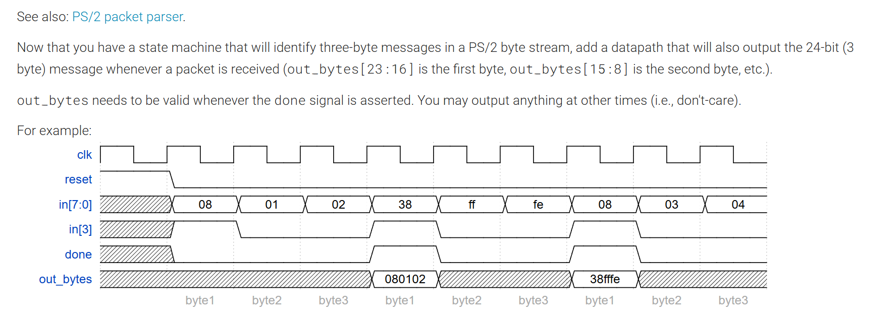
题目分析
一个完整的状态机通常包含三类信号:
| 信号类别 | 例子(本题) | 更新时机 | 逻辑类型 |
|---|
| 状态寄存器 | state | 只在时钟上升沿更新 | 时序逻辑 |
| 次态计算 | next_state | 由当前状态和输入随时决定 | 组合逻辑 |
| 输出信号 | done, out_bytes | 题目要求 done 在固定周期有效,out_bytes 需要保持完整消息 | 有时序/组合两种可能 |
out_bytes 必须保存完整的三字节消息,直到下一个 done 有效。- 由于消息的字节不是同时到达的,而是分三个时钟周期依次到来,所以必须用寄存器来存储它们,否则数据会丢失。
- 因此
out_bytes 必须用时序逻辑(寄存器)来实现。
可是寄存器要更新,又不能在 done 有效时被新数据破坏。所以你看到的正确解法中,out_bytes 的赋值在每个时钟上升沿发生,但利用非阻塞赋值的特性确保:
- 在接收消息的三个周期内,依次填入字节。
- 在
done 周期(即状态 DONE)中,虽然也执行了 out_bytes[23:16] <= in,但当前周期输出的是旧值(完整消息),而 in 是新消息的第一个字节。等下一周期 state 退回到 BYTE1,输出才会被新消息覆盖。
这正是时序逻辑的典型应用:需要“记忆”历史值。
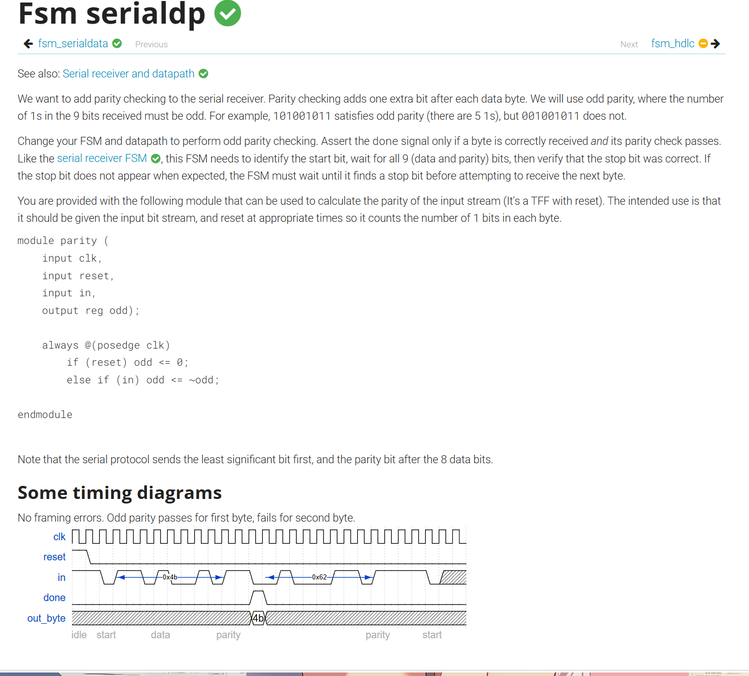
处理数据的状态机
下一刻的状态和我们存储的数据有关,有不同的方法来处理,尽量选择简单的方法
 1
 2
 3
 4
 5
 6
 7
 8
 9
10
11
12
13
14
15
16
17
18
19
20
21
22
23
24
25
26
27
28
29
30
31
32
33
34
35
36
37
38
39
40
41
42
43
44
45
46
47
48
49
50
51
52
53
54
55
56
57
58
59
60
61
62
63
64
65
66
67
| module top_module(
input clk,
input in,
input reset, // Synchronous reset
output [7:0] out_byte,
output done
); //
// Use FSM from Fsm_serial
parameter idle = 0,get = 1,stop = 2,right = 3,error = 4,judge = 5;
reg [3:0] state,next_state;
reg [7:0] count;
reg [7:0] outdate;
always@(*)begin
case(state)
idle: next_state = in? idle:get;
get: next_state = (count == 8)? judge : get;
judge: next_state = (odd_reg ^ in)? stop : error;
stop: next_state = in? right : error;
right: next_state = in? idle : get;
error: next_state = in? idle : error;
default: next_state = state;
endcase
end
always@(posedge clk)begin
if(reset)begin
state <= idle;
end
else state <= next_state;
end
always@(posedge clk)begin
if(reset) count <=0;
else begin
case(next_state)
get:begin
count <= count + 8'd1;
end
default:begin
count <= 8'd0;
end
endcase
end
end
assign done = (state == right);
// New: Datapath to latch input bits.
always @(posedge clk) begin
if(reset) outdate <= 8'd0;
else begin
outdate[count - 1] <= (state == get)? in : 1'd0;
end
end
assign out_byte = outdate;
// output declaration of module parity
wire odd;
wire r_reset = (state == idle) || (state == judge) || (state == stop) || (state == right) || (state == error);
parity u_parity(
.clk (clk),
.reset (r_reset),
.in (in ),
.odd (odd_reg)
);
reg odd_reg;
endmodule
|
这里是通过1个数奇偶来判断的,相对来说比较简单,最开始1的个数为0,每多一个1就反转就行了,其实和历史状态没什么关系了,相当于把历史状态转化为了目前的状态
看一下另一道题目
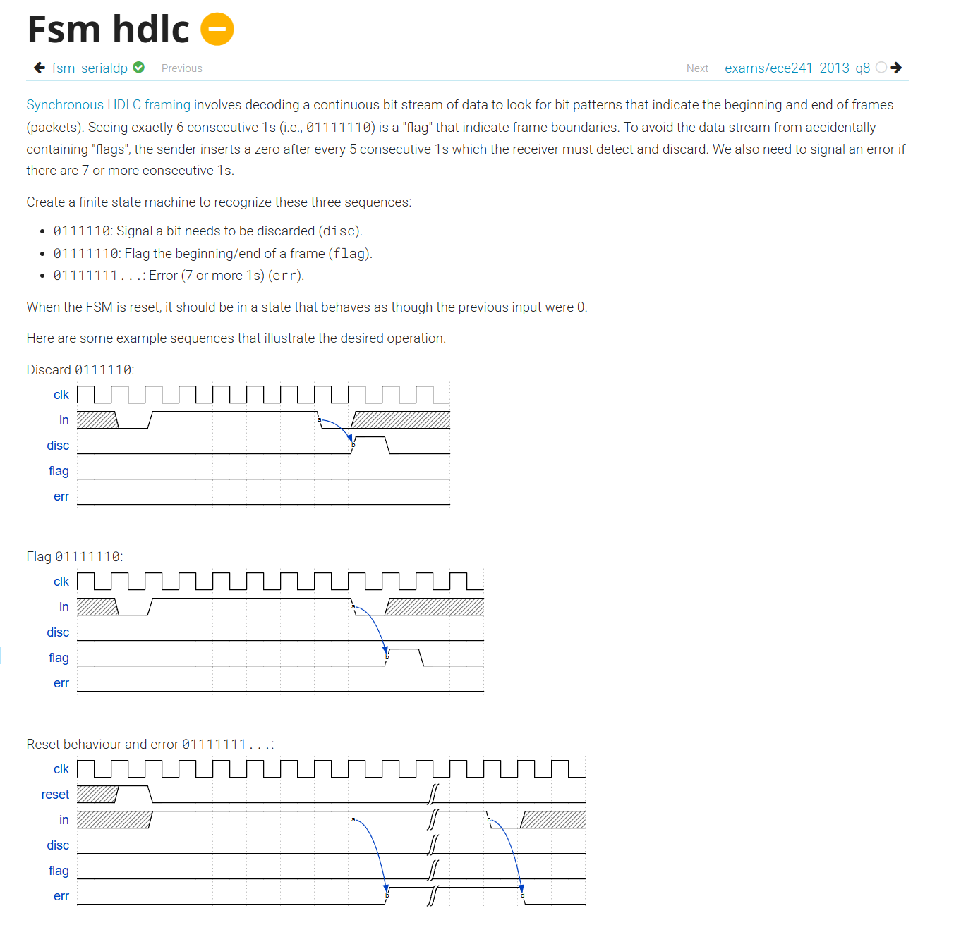
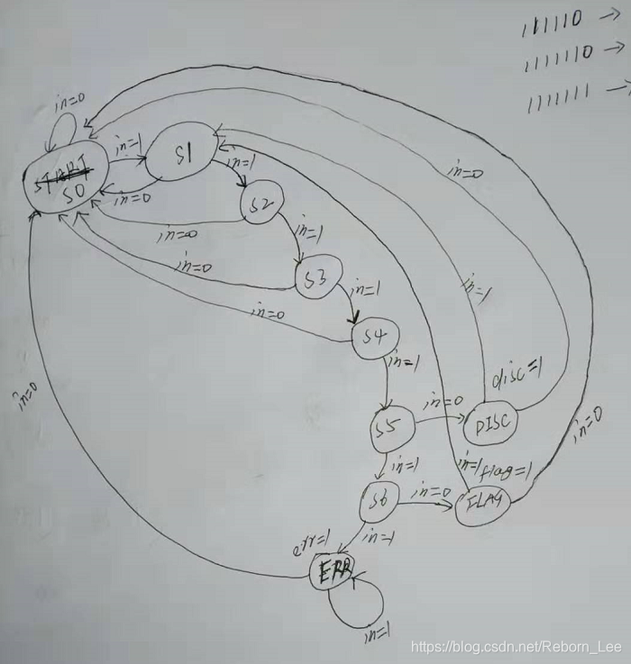
这道题暴露了我没有理解状态机的本质,我企图记录数个历史状态来判断下一个状态,这不符合状态机的思想
每个时钟周期只处理当前到来的一个比特,而不是累积多个比特后再处理,这是状态机设计中的核心原则。
以后设计的时候不能违背这个核心原则,将正确代码和状态转化图附上:
 1
 2
 3
 4
 5
 6
 7
 8
 9
10
11
12
13
14
15
16
17
18
19
20
21
22
23
24
25
26
27
28
29
30
31
32
33
34
35
36
37
38
39
40
41
| module top_module(
input clk,
input reset,
input in,
output disc,
output flag,
output err
);
// 状态定义:使用独热码或二进制编码
parameter IDLE = 0, ONE = 1, TWO = 2, THREE = 3, FOUR = 4, FIVE = 5, SIX = 6,
ERROR = 7, DISCARD = 8, FLAG = 9;
reg [3:0] state, next_state;
// 次态组合逻辑
always @(*) begin
case(state)
IDLE: next_state = in ? ONE : IDLE;
ONE: next_state = in ? TWO : IDLE;
TWO: next_state = in ? THREE : IDLE;
THREE: next_state = in ? FOUR : IDLE;
FOUR: next_state = in ? FIVE : IDLE;
FIVE: next_state = in ? SIX : DISCARD;
SIX: next_state = in ? ERROR : FLAG;
DISCARD: next_state = in ? ONE : IDLE;
FLAG: next_state = in ? ONE : IDLE;
ERROR: next_state = in ? ERROR : IDLE;
default: next_state = IDLE;
endcase
end
// 状态寄存器
always @(posedge clk) begin
if (reset) state <= IDLE;
else state <= next_state;
end
// 输出
assign disc = (state == DISCARD);
assign flag = (state == FLAG);
assign err = (state == ERROR);
endmodule
|